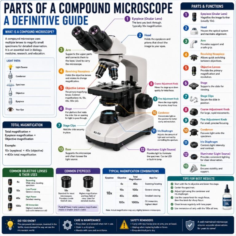
Pick up a compound microscope for the first time and it can feel overwhelming — there are knobs on the side, a rotating turret at the bottom of the head, and a cluster of lenses you’re not sure whether to touch. Once you know what each part does and why it’s there, operating the scope becomes intuitive, and you stop worrying about breaking something expensive. This guide walks through every part of a compound microscope in the order you’ll actually encounter it, from eyepiece to base, with the practical detail that textbook diagrams leave out.
What Is a Compound Microscope — and How Does It Work?
Before getting into the individual parts, it helps to understand the machine as a whole. These three foundational questions set up everything that follows.
What is a compound microscope?
A compound microscope is a high-magnification optical instrument that uses two or more lenses in series to produce an enlarged image of a specimen too small to see with the naked eye. It gets the name “compound” from that two-lens (or multi-lens) arrangement: one lens magnifies the specimen, and a second lens re-magnifies that image.
Compared to a compound light microscope versus simpler designs, the compound scope achieves far higher magnification than a simple microscope — the single-lens type first built by Antonie van Leeuwenhoek in the 1670s and described in Robert Hooke’s Micrographia (1665). You’ll find compound microscopes in high school biology labs, university research facilities, clinical pathology departments, and quality-control labs across manufacturing and food science.
How does a compound microscope work?
Light from the illuminator in the base travels upward through the condenser, which focuses it into a cone aimed at the specimen on the stage. The light passes through the specimen (or reflects off it, for opaque samples), enters the objective lens just above the stage, and gets magnified. That magnified image then travels up the eyepiece tube to the ocular lens in the eyepiece, which magnifies it a second time. The result is a bright, high-contrast image floating in the eyepiece field of view.
The two-lens arrangement is what pushes magnification into ranges — 40×, 100×, 400×, up to 1000× — that a single-lens design can’t reach.
What is a compound microscope used for?
Its high magnification makes a compound microscope the right tool for viewing small specimens whose detail is invisible to the naked eye: cells, cell organelles, bacteria, blood films, tissue cross-sections, and microorganisms. It is an affordable yet powerful instrument used by students, biologists, medical professionals, and researchers in fields ranging from bacteriology to forensics. You’ll also find it in settings like quality control for pharmaceuticals and food safety testing for microorganisms.

The Parts of a Compound Microscope
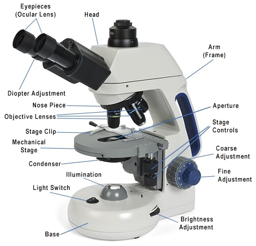
A compound microscope has more moving pieces than it first appears. Its parts fall into two functional categories: optical components (lenses and the light path) and structural or mechanical components (the frame, knobs, and stage that hold everything in position). Physically, the microscope is organized into three sections — the head at the top, the body (arm) in the middle, and the base at the bottom. Here is every part, where it lives, and what it does.
The Head
The head is the uppermost section of the microscope. It houses the optical systems you look through and the lens turret below them. On most compound microscopes the head is fixed; on some research models it can tilt. Everything in the head is optical — this is where magnification begins and ends.
Eyepiece
The eyepiece — also called the ocular lens — is the lens you look through directly. It sits at the top of the eyepiece tube and re-magnifies the image already produced by the objective lens below. That second magnification is what makes the compound design so powerful.
When you first look through the eyepiece on a new scope, the field of view appears as a bright disc surrounded by darkness. If it looks soft or double, the diopter ring (described below) needs adjustment. A well-focused eyepiece gives a crisp, glowing circle of image — almost like a tiny illuminated window.
The standard eyepiece magnification is 10×. Some scopes ship with 5× or 15× oculars, and high-zoom models offer variable-magnification eyepieces up to 30×, though these are uncommon in routine lab work.
Monocular vs. Binocular vs. Trinocular — Choosing the Right Head
The eyepiece configuration has a bigger impact on your workflow than most buyers anticipate. Here is a quick comparison:
| Type | Eyepiece tubes | Best for | Drawback |
|---|---|---|---|
| Monocular | 1 | Budget entry-level use, lightweight portability | One eye closed the whole time; camera integration is impractical |
| Binocular | 2 | Most classroom, clinical, and routine lab work | Camera attachment requires an add-on C-mount adapter |
| Trinocular | 3 (third is camera port) | Teaching, documentation, research requiring simultaneous live view and imaging | Most expensive; heavier head |
Binocular is the standard choice for most users. The ability to view with both eyes reduces eye strain significantly during long sessions — you’ll feel the difference after the first 20 minutes.
Eyepiece Tube
The eyepiece tube is the hollow metal barrel that connects the eyepiece to the interior of the head. Light travels up through it from the objective lens. On binocular and trinocular heads, the two tubes are housed in a hinged unit that can be spread or narrowed to match the distance between your eyes — this is the interpupillary adjustment described next.
Diopter Adjustment
The diopter adjustment ring sits just below one eyepiece (usually the left on binocular heads). Its job is to compensate for differences in vision between your two eyes.
To use it: close the adjusted eye, focus normally with your other eye using the coarse and fine knobs. Then close the first eye, open the adjusted eye, and turn only the diopter ring — not the focus knobs — until the image is sharp. Once set, the diopter is rarely touched again unless a different person uses the scope.
Interpupillary Adjustment
On binocular and trinocular heads, the eyepiece tubes can be spread apart or pulled together to match the distance between your pupils. This distance — the interpupillary distance (IPD) — varies among adults, typically 48 to 75 mm, with most people falling between 55 and 70 mm. You adjust it by gently pulling or pushing the two eyepiece barrels laterally until the two separate circles of light merge into a single, unified field. If you see two overlapping ghost images, keep adjusting. The correct setting feels obvious — everything snaps into one clean view.
Revolving Nosepiece
At the lower end of the head, the revolving nosepiece (also called the turret) is a rotating disc with three to five threaded positions, each holding an objective lens of a different magnification. Rotate it and you’ll hear and feel a distinct click as each objective locks into the optical axis — that click confirms the lens is centered and aligned with the eyepiece above.
Rotate the nosepiece by gripping its outer edge, not by grabbing the objective lens barrels, which can loosen the lenses over time.
Objective Lenses
The objective lens is the primary magnifying element of the microscope. It sits closest to the specimen, collects light passing through the sample, and produces the first (real) magnified image that the eyepiece then re-magnifies. A typical compound microscope ships with four objectives:
- 4× (scanning): low magnification, wide field of view — good for finding and centering the specimen
- 10× (low power): the starting lens for most observations; covers a useful area of the slide
- 40× (high-dry): the workhorse objective for detailed cell work without immersion oil
- 100× (oil-immersion): maximum magnification, requires immersion oil — see below
Always begin observation at 4× or 10× and move up through the magnifications in sequence. Going straight to 40× or 100× on an unfocused specimen wastes time and risks hitting the slide with the lens.
Objective lens classes — achromat vs. plan-achromat
Objectives come in optical grades. The most common:
- Achromat: corrects chromatic aberration for two wavelengths; the most affordable class. The center of the field is sharp; edges may show some curvature. Standard in school and entry-level lab scopes.
- Plan-achromat: adds field flatness correction so the entire image from edge to edge is in focus simultaneously. The standard choice for clinical and research work where you need to scan across the slide without refocusing.
- Fluorite / semi-apochromat and apochromat: correct chromatic aberration for three or more wavelengths; used in fluorescence, photomicrography, and demanding research applications. Significantly more expensive.
For most biology and pathology work, plan-achromat objectives are the practical choice. The “plan” prefix is usually visible on the barrel label.
The 100× oil-immersion objective
The 100× objective is different from the others in one critical way: it requires a drop of immersion oil placed between the lens tip and the cover slip before use.
Without oil, light refracts (bends) as it passes from the glass cover slip into the air gap before entering the lens, which scatters the light and degrades the image. Immersion oil has nearly the same refractive index as glass (~1.515), so light travels straight through without bending, maintaining the cone angle needed for maximum resolution. Running the 100× objective “dry” — without oil — produces a noticeably worse image than the 40× below it, which is the clearest sign something is wrong.
Apply a single small drop of immersion oil to the cover slip (not to the lens). After use, wipe the oil off the objective immediately with lens tissue — oil left to dry on the glass is much harder to remove cleanly.
Numerical aperture (NA) — what actually limits your image
Engraved on every objective barrel alongside its magnification is an NA figure, such as “40×/0.65” or “100×/1.25 oil.” NA is the most important optical specification of the objective, because it sets the resolution limit — the minimum distance between two points the scope can distinguish as separate.
Higher NA = finer detail. The 100× oil objective reaches NA ~1.25, which is why oil is necessary: oil is the only way to get light into the lens at the steep angle needed to push NA above 1.0 (the maximum possible in air). The 40× high-dry objective typically has NA 0.65; the 10× scanning lens may have NA 0.25.
This also explains why “more magnification” is not the same as “more detail.” The useful magnification limit is approximately 1000 × NA. Beyond that you get empty magnification — the image gets bigger but no new detail appears because the lens simply cannot resolve it. For a standard 100× oil objective (NA 1.25), the practical working ceiling is about 1000×. A 20× eyepiece pushing to 2000× with the same objective would show a larger, blurrier image, not a sharper one — this is called empty magnification.
The Body (Arm)
The body — often called the arm — is the vertical column connecting the head to the base. It is the structural backbone of the microscope and the part you grip when carrying it. Always carry a compound microscope with one hand on the arm and one hand supporting the base — never by the eyepiece or the stage.
The body also holds the focus adjustment system and the specimen stage.
Adjustment Knobs
Two knobs on the side of the arm control focus by moving the stage (or on some designs, the head) up and down:
Coarse adjustment knob — the large outer knob. It moves the stage in coarse increments and is used to bring the specimen roughly into focus at low power. At low magnification (4× or 10×), the coarse knob gives you a wide range of movement and won’t damage anything because the working distance (gap between lens and slide) is large.
Fine adjustment knob — the smaller inner knob (or on some designs, nested inside the coarse knob on the same axis — “coaxial” design). It moves the stage in very small increments to sharpen the image after coarse focus. At high magnification, the fine knob is essentially the only knob you use.
The most common beginner mistake with focus knobs: using the coarse knob at high magnification while looking through the eyepiece and focusing down toward the slide. At 40× the working distance is under a millimeter — a single half-turn of the coarse knob can drive the objective straight into the cover slip and crack the slide (and scratch the lens). The rule is: always focus up and away from the slide, especially at high power. On many modern scopes the coarse knob disengages or stiffens at high-power settings to protect the objectives from exactly this mistake.
Specimen Stage
The stage is the flat platform, usually metal, where you place the glass specimen slide. It sits between the objectives above and the condenser below, and it is where most of the mechanical action in everyday microscopy happens.
Aperture
In the center of the stage is a circular opening — the aperture — through which light from the condenser below reaches the specimen and then the objective lens above. When loading a slide, center the specimen over this aperture. A specimen slide placed with the specimen over an opaque part of the stage simply won’t illuminate.
Stage Clips
On simpler or older models, two spring-loaded metal clips on the stage edges hold the slide in place. They work, but they limit you to sliding the specimen manually — often an awkward, imprecise affair at 40× where the field of view is a tiny fraction of the slide area.
Stage Control (Mechanical Stage)
Most mid-range and higher compound microscopes replace stage clips with a mechanical stage: a two-axis control system with dedicated knobs (usually stacked) that move the slide precisely left/right and forward/back. Once you’ve used a mechanical stage at 400×, going back to manual clips feels impossible.
The stage control knobs are low-torque — you can feel resistance if a slide is not properly seated, which prevents you from forcing the glass against the objective.
Rack Stop
The rack stop is a small adjustable screw or collar that limits how far down the stage can travel toward the objective lenses. It is factory-set to prevent the 4× or 10× objective from crashing into a standard-thickness slide. Do not loosen it without a specific reason — it is a safety limiter, not a normal user adjustment.
The Base
The base is the weighted bottom of the microscope. Its mass keeps the scope stable on the bench — tipping risk is essentially zero even on a heavy trinocular scope. The base houses the illumination system and its controls.
Light Source
The illuminator (light source) provides the light that makes everything else possible. It shines upward through the condenser and specimen into the objective lens.
LED is now the standard illuminator on current compound microscopes. LEDs are energy-efficient, generate very little heat, have a stable color temperature close to daylight, and last tens of thousands of hours — you are unlikely to ever replace a bulb during normal use. Older scopes use low-voltage halogen bulbs, which run hotter and produce a warmer (more yellow) light; even older designs used a mirror to redirect ambient light. If you are buying a new scope, expect LED.
Most illuminators include a rheostat (brightness dial) that adjusts light intensity. Start at medium brightness; cranking it to maximum is rarely necessary and bleaches the image.
Condenser
The condenser is mounted below the stage, between the light source and the aperture. Its job is to collect diverging light from the illuminator and concentrate it into a focused cone aimed precisely at the specimen. Without the condenser, light would scatter instead of focusing, and the image at high magnification would be dim and diffuse.
The Abbe condenser — named for Ernst Abbe — is standard on most mid-range and routine lab compound microscopes. It may have a condenser focus knob that moves it up or down; raise it toward the stage for optimal illumination at high power.
For the best image quality at any magnification, set up Köhler illumination (described in the Usage section below). Most beginners skip this, which is exactly why their high-magnification images look flat.
Iris Diaphragm
Between the condenser and the stage aperture sits the iris diaphragm — a variable aperture built from overlapping metal blades, identical in concept to the aperture in a camera lens.
It is a common mistake to think of the iris diaphragm purely as a brightness control. Its primary function is to control the angle (cone) of light entering the condenser, which directly sets the working numerical aperture of the illumination — governing image resolution and contrast, not just brightness.
Open the iris too wide: you get maximum brightness but lower contrast (fine for thick, stained specimens). Close it too far: contrast increases but resolution drops and diffraction artifacts appear. The practical rule is to adjust the iris until it fills about 70–80% of the objective’s back aperture — a setting you verify through a Bertrand lens or by removing the eyepiece and looking down the tube. More detail on iris adjustment is in our iris diaphragm guide.
Power Switch
The power switch turns the illuminator on and off. On most scopes it is located on the base near the light intensity dial. Turn off the illuminator when you finish a session — even LEDs benefit from not running unnecessarily, and it trains good lab habits.
How to Calculate Total Magnification
One of the most common questions beginners have — and one the original article strangely omitted — is how to calculate the actual magnification they are using. It is simple:
Total magnification = Eyepiece magnification × Objective magnification
| Eyepiece | Objective | Total magnification | Typical use |
|---|---|---|---|
| 10× | 4× | 40× | Scanning for specimen location |
| 10× | 10× | 100× | Initial viewing, tissue overview |
| 10× | 40× | 400× | Cell morphology, fine tissue detail |
| 10× | 100× (oil) | 1000× | Bacteria, blood smears, fine organelle detail |
The realistic maximum for a standard compound microscope is 1000×. Going beyond this — for example, using a 20× eyepiece with a 100× objective to reach 2000× — produces empty magnification: the image is larger but no finer detail is revealed, because the objective lens cannot resolve detail smaller than its NA allows. The image just looks bigger and blurrier.
How to Use a Compound Microscope

Now that the parts make sense, here is the correct operating sequence — including the steps most beginner guides skip:
- Carry it correctly. One hand grips the arm, the other supports the base. Never carry it by the eyepiece or the stage.
- Start on low power. Rotate the nosepiece until the 4× objective clicks into place. Look through the eyepiece — you should see a bright, empty circle of light. If not, turn on the illuminator and open the iris diaphragm.
- Prepare and load the slide. Place the specimen on a glass slide. If working with a wet specimen, add a drop of mounting medium and a cover slip to protect both the specimen and the objective — see our guide on wet mount slides for the full technique. Mount the slide with the specimen centered over the stage aperture. Secure with stage clips or the mechanical stage arm.
- Rough focus at 4×. Looking from the side of the microscope (not through the eyepiece), use the coarse adjustment knob to lower the stage toward the 4× objective until it is about 1 cm from the slide. Then look through the eyepiece and slowly raise the stage (moving away from the objective) until the specimen comes into view. Refine with the fine knob.
- Set up Köhler illumination. Once the specimen is in focus at low power, raise the condenser to near the top of its travel. Close the field diaphragm (if present), center the condenser so the field diaphragm image is centered in the field of view, then open it until it just clears the field edges. Adjust the iris diaphragm for contrast. This one step improves image quality more than any other adjustment most beginners ever make — a full walkthrough is available in Scientifica’s Köhler illumination guide.
- Move up through objectives. Advance to 10×, re-center the specimen, then refocus with the fine knob. Move to 40× the same way. The specimen will stay roughly in focus (parfocal design) but always check with fine focus after switching.
- Using the 100× oil objective. Place a single small drop of immersion oil on the cover slip directly over the specimen. Rotate the 100× objective into position until it gently contacts the oil — you will see the field brighten as the oil fills the gap. Focus with the fine knob only. Never use the coarse knob at 100×.
- Shut down correctly. Lower the stage, remove the slide, wipe immersion oil from the 100× objective immediately with a clean lens tissue. Rotate the nosepiece back to 4×. Turn off the illuminator. Cover the microscope with a dust cover before storing.
Care and Maintenance
A compound microscope is a precision optical instrument. It does not need much maintenance, but the maintenance it does need matters:
- Lens cleaning: Use only optical-grade lens tissue or a dedicated lens cleaning cloth. Never use paper towels, clothing, or facial tissue — these contain wood fibers that scratch optical coatings. For stubborn residue, a drop of lens cleaning solution (methanol-based) on lens tissue, not applied directly to the glass. Wipe in a single circular motion, not back and forth.
- Immersion oil: Clean the 100× objective after every use. Oil left to dry polymerizes and is extremely difficult to remove. If this happens, a small amount of xylene on lens tissue can dissolve it — but test on the outside barrel first and never use xylene near rubber seals.
- Dust: Keep the scope covered when not in use. Dust on internal optics is hard to remove without disassembly. Dust on the external surface of objectives can be blown away with a rubber air bulb before using lens tissue.
- Storage: Store the scope with the lowest-power objective in position and the coarse knob backed off. A dry, stable temperature environment prevents fungal growth on optics — a real risk in humid conditions.
Frequently Asked Questions
What are the three main sections of a compound microscope?
Head (top section, houses the eyepiece and objective lenses), body/arm (middle section, structural column holding the focus knobs and stage), and base (bottom section, houses the illuminator, condenser, and power switch).
What is the function of the eyepiece on a compound microscope?
The eyepiece (ocular lens) is the second magnification stage. It takes the real image already formed by the objective lens and magnifies it a second time before your eye. Standard magnification is 10×. The eyepiece also allows diopter adjustment to correct for differences in vision between eyes.
What does the objective lens do?
The objective lens is the primary magnifier. It collects light that has passed through the specimen and forms a magnified real image inside the microscope body. The objective’s numerical aperture (NA) determines the resolution — the finest detail the scope can reveal.
What is the difference between coarse and fine focus knobs?
The coarse focus knob moves the stage in large increments for initial focusing, used primarily at low magnification. The fine focus knob moves the stage in tiny increments for precise sharpening at high magnification. Always start with coarse at low power, then switch to fine when moving to higher objectives.
What is the function of the iris diaphragm?
The iris diaphragm controls the cone angle of light entering the condenser. This sets the working numerical aperture of the illumination, governing both resolution and contrast. It is not simply a brightness control — closing it too far reduces resolution even as it increases contrast.
Why does the 100× objective need immersion oil?
Without oil, light refracts (bends away) when it crosses from the glass cover slip into the air gap before the lens, reducing the cone angle the objective can capture and dropping the NA below 1.0. Immersion oil has nearly the same refractive index as glass, so light travels straight through, allowing the 100× objective to reach NA values of 1.25 and above — the level needed for resolving bacteria and fine subcellular structures.
What is the difference between a compound microscope and a stereo microscope?
A compound vs stereo microscope comparison comes down to magnification and specimen type. Compound microscopes use transmitted light and thin, transparent specimens at 40×–1000×. Stereo microscopes use reflected light, can examine opaque, three-dimensional objects at low magnification (typically 7×–45×), and give a stereoscopic (3D) view. They serve completely different purposes.
What is the maximum magnification of a compound microscope?
The practical maximum is 1000× using a 100× oil-immersion objective and a 10× eyepiece. Beyond this you hit empty magnification — the image enlarges but gains no new detail because light-microscope resolution is limited by the wavelength of visible light and the objective’s NA. Electron microscopes are the tool for anything beyond what light optics can resolve.
Summary
A compound microscope is a high-magnification optical instrument whose power comes from a two-lens system: the objective lens (primary magnification, governs resolution via NA) and the ocular lens (secondary magnification). Its parts divide into optical components — objective lenses, eyepiece, condenser, iris diaphragm — and structural components — arm, stage, focus knobs, and base — arranged across three sections: head, body, and base.
Understanding what each part does makes the difference between a frustrating experience and one where you get a clean, sharp image every time. Start on low power, work up through objectives in sequence, set up Köhler illumination, use immersion oil on the 100× objective, and clean the optics after every session. That is the complete loop — from knowing the parts to using them correctly.
For related reading, see our guides on types of microscopes, how to prepare microscope slides, and microscope resolution.